Note: this article originally appeared on TeamUV.org
Stress concentrations (commonly referred to as stress risers or raisers) are areas in a material that, owing to problematic geometry, lead to…well, greater stress concentration in portions of the material/part. These concentrations can be great headaches to engineers, as the localized concentration of the stress means the part experiences much higher stresses in said specific regions than the average stress in the material as a whole (or than the material would experience without the riser), which can lead to failure at much smaller loadings than originally thought. Well what in the world does that mean?
To better explain this, we will examine a very simple case: pure tension in a rectangular sample. Imagine that you take a rectangular bar and pull on it along it’s axis, as shown below. We will make some simplifying assumptions for the purpose of ease of demonstration; assume that when you pull on the sample, you pull on the entire end face equally; that is, you distribute the loading across the entire face equally. Also assume that the material is homogenous (the same physical & mechanical properties at all points throughout the material), isotropic (the same properties in all directions), and uniform in cross-section (the cross-sectional size/shape does not change along the bar’s length). These assumptions will hold for demonstration and are sometimes used in applications in which strength is not of major concern, but generally speaking, it will be very difficult to apply a load evenly across a surface (picture gripping a piece of metal with a pair of pliers…the grip point is the point of load application and does not cover the entire face, but rather is localized), materials will never be homogenous (due to voids, inclusions, and other manufacturing/processing defects), many materials will not be isotropic (a piece of un-altered steel is ideally isotropic, but wood, for example, has directional strength in the directions of its “grains”; many other materials also express different properties in different directions), and many geometries will betray the assumption of uniform cross section (as we will see shortly).
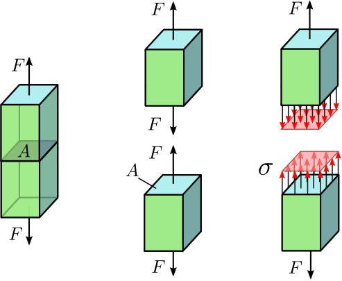
Photo Credit: Wikipedia.org
When we pull on the material, that force is transmitted through the material with an equal and opposite reaction internal to the material, as shown in the center image of the above picture. This force may be shown as a single resultant force vector (like in the center image), but is actually distributed over the entire inside of the material (as shown in the right/3rd image). When this load/force acts over this area (and remember, we are only looking at pure tension…the load is applied perfectly perpendicular to the material cross section, as otherwise we would induce bending), it creates a normal stress that is defined as the applied load divided by the cross-sectional area. Under the assumptions we made before, this should mean that every point in the material experiences the same normal stress, meaning that in order for the material to fail, the average normal stress in the material needs to exceed the failure strength (in this case, the applicable tensile strength).
But what happens when we apply a stress concentration, by introducing a discontinuity in the geometry (i.e. a crack, sharp edge/corner, or change in cross-sectional area)? The stress distribution can no longer be uniform, as the loading has to be re-routed to avoid the discontinuity as it travels through the material (for the case of geometric stress concentration), as shown for the simple case of a circular hole in the material below.
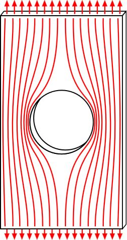
As can be seen, the distribution tends to bunch up around the hole, creating a higher concentration of stress. From a mathematical standpoint, the local normal stress in the region of the hole has also increased as the cross-sectional area of the sample at the hole location is now less (imagine cutting the bar in half perpendicular to the loading and looking at it from the end…instead of being the full rectangular cross-section of before, there is material missing), thus the normal stress is higher because we are applying the same load, but now are dividing it by a smaller area than before. This means that if we apply a loading to the uniform sample that created a stress under the tensile strength of the material before, that materials would not fail, but now if we apply the same exact loading to this new sample with the stress riser, the sample could very well fail due to the heightened stress at the discontinuity. This should be seen as quite alarming as this means that parts can fail at lower loadings than expected, and while our example shows a huge hole in the part, it should be noted that small cracks, or simply sharp corners and other minimal, yet abrupt changes in the geometry can affect the state of stress in a major way.
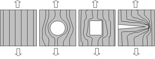
We should also note that highly concentrated stress regions can be formed by applying loads non-uniformly, as in the example of gripping material with pliers discussed in the 2nd paragraph, where we apply a load on a very localized, concentrated region (picture taking a 10 lb weight and placing it directly on a table vs. taking the same weight, balancing it on a thumbtack, and then placing it on the table with the tack point down). Just as before, we have decreased the effective area that the load is applied over, except this time, we reduced the area of the stress region by changing how the load was applied, whereas before we did it by changing how the load was transmitted.
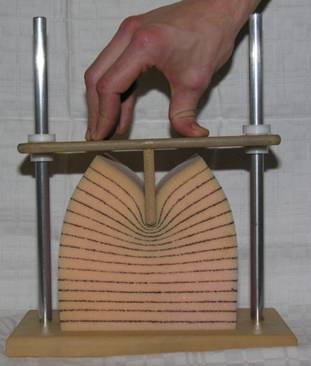
For this reason, engineers must be very careful when they design parts to include factors of safety to account for material imperfections, possibly use non-destructive inspection (NDI) techniques to examine critical parts for cracks in situations where a crack could prove catastrophic (for example a crack in the side wall of a submarine hull that could spread due to cyclic fatigue due to cycles of compression/de-compression when traversing great depths, surfacing, sinking again, surfacing again, etc.), and must avoid abrupt changes in geometry in the design of the part itself. Luckily, in this day and age, we understand much more about internal stresses and stress distribution thanks to new testing and stress visualization techniques, but the subject of stress concentrations is one that I cannot stress the importance of enough! (I apologize for the bad pun)

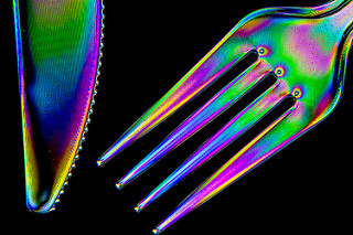
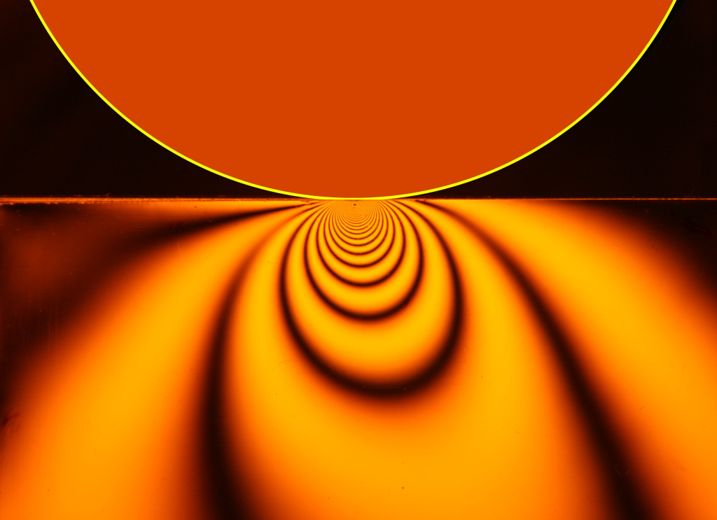
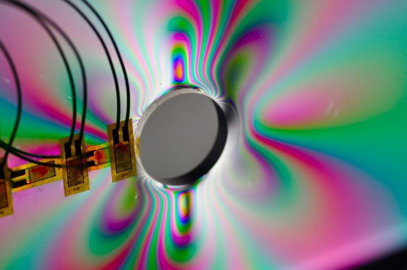
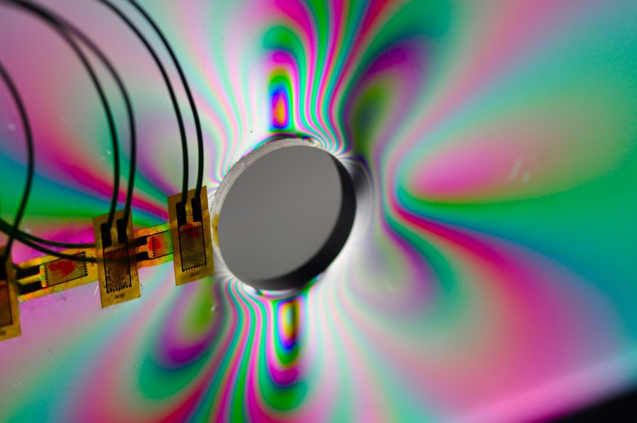
Additionally, this was purely looking at one-dimensional loading in an over-simplified material and geometry, but in the real world we can have parts of really intricate geometry, made from materials with unbelievable amounts of anisotropy (different properties in different directions), subjected to combined three-dimensional loading of tension, bending, torsion, shear, perhaps compression in a different region, with hygrothermal loading (loading due to both moisture and thermal effects), subjected to different kinds of corrosion, vibrational modes, impact loading, and the list just goes on and on! Anyways, hopefully today you learned a little bit more about one of the endless topics that engineering encompasses! I will leave you with some really cool photoelastic stress visualization pictures in which the refraction of light is a function of stress (due to birefringence), thus the material essentially shows different wavelengths (and thus different colors) due to differences in stress throughout the material, helping to visualize stress (and stress concentrations).

